Two types of switching for our GlidewayPRT system.
Two separate switching systems (single rail non-leveling, and multi-rail leveling) will be tested to determine which is most effective for GlidewayPRT. Both systems use vertical switches which require using wide gauge tracks and wheels. Switching is achieved by a separate set of tracks laid outside of and parallel to, and at the same level as the main line.
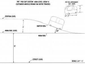
The basic single rail switch enables PRT vehicles to separate from the main line by extending their driving wheels further out from the sides of the vehicle, engaging a second set of wider gauge parallel rails and riding them up a ramp to the next level (the station level.) It requires all four axels and wheels being extended further out of the sides of the PRT vehicle at a precise predetermined location on the main line just prior to arriving at the switching position. These extended extra wide wheels will ride on both the additional track and the main line at the same time, temporarily, at the same level, and parallel to the main line. These four wheels are extra wide, with cone shaped treads and slightly smaller diameter at the center of each tread, similar to railroad wheel treads.
The exit ramps and switching rails have a wider gauge than the width of the PRT vehicles so successive vehicles not exiting to a particular station will proceed between the switching and exit rails without having to reduce speed.
An exiting vehicle does not have to slow down from its standard speed to enter a ramp and drive up to the PRT station. In order to conserve horizontal space and speed up this processing of passengers, we have designed most stations to be elevated about 6 feet above the main line. This requires more energy going up, but that energy will be recouped coming back down, and it means more space for the public and temporary storage of 6 or 7 empty and ready vehicles. The limited footprint also allows for more floor space inside the associated department store, business building, etc.
An automated control system will keep track of the location of all vehicles at all times. This system will use the same control system as the Bimodal Glideway System where every few feet of the track there is a bar graph visible to the GlidewayPRT vehicle’s receiver which establishes its precise location, movement, acceleration, speed, and other operational information as determined important to the operation of the system. All this information is automatically transferred to the local PRT center controlling a district and all of its PRT vehicles. The PRT center redistributes the vehicles where needed when indicated by users/conditions and projected demands.
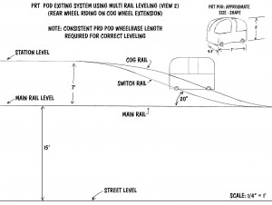
The second system (multi rail leveling switch) uses a third set of auxiliary rails and an additional cog, or high friction wheel at the end of the axles. This unique switching system allows vertical switching while maintaining the horizontal position of the PRT pod while exiting or entering the system. During exit or re-entry into the system, the PRT pod’s cog wheels extend out to catch the cog rail at the end of the pod which is furthest from the station. Pods exiting the system will engage the cog rail with the rear cog wheels, and pods re-entering the system will engage the cog rail with the front cog wheels.
This switching reduces the horizontal platform area needed by permitting a steeper slope for the exiting/entering ramps. It also requires more power and a cog wheel/guideway or high traction wheel/ramp system for the third rail. If used throughout a PRT system it can contribute to reducing turnaround time and reduced costs (less elevated horizontal space).
An additional advantage of adding a third, switching, rail is reduced the exit and entry ramp length, thereby increasing the floor area of elevated PRT stations
This figure shows 3 different ramp angles at 10, 20 and 30 degrees, depending on comfort for seated passengers. If using a steeper entry/exit ramp of 30 degrees and keeping the vehicle horizontal, the loss of station floor space is about 60 square feet at the ramp entrance and 60 square feet at exit, i.e., 120 square feet total. If using an entry/exit ramp of 10 degrees it will increase to about 160 plus 160 or 320 square feet. Since all stations are elevated this added surface area is important.